
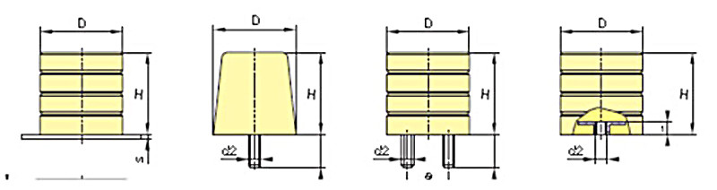
Bumpers
Bumpers for railways, wagons, cranes, travelling carts, trailers, rack chargers, loading platforms, and container tranship centres and ports.
For Industrial energy absorption
1: Hydraulic – gas
Typical examples of application:
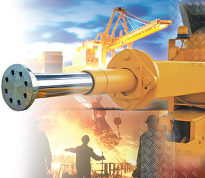
- Cranes
- Steel works
- Rolling mills
- Ports
- Container tranship points
- Transport
- Bridges
- Sea drilling rigs
- End
- Army
- Mines
- Railways
Hydraulic – gas bumpers
are the most economic and offer the best way how to “destroy” the excess energy.
- They protect your equipment in optimal way.
- They reduce the risk of accident, injury or collision.
- They reduce maintenance costs.
- They are made with highest precision.
- They have very long service life.
- Their application is broad.
- They need nearly no maintenance.
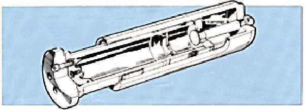
How the hydraulic – gas bumper works?
The hydraulic-gas bumper is made from a cylinder (Zylinder) and a piston (Plunger) filled with hydraulic oil and nitrogen as the figure shows. The hydraulic oil and nitrogen are separated by movable piston (Kolben).
When the piston (Plunger) hits the obstacle, it is pushed into the cylinder. Thus compressed hydraulic oil is lead from the chamber A to the chamber B through an exactly determined throttling bore.
With the increased content of the chamber B the movable piston (Kolben) is pushed in the shock direction. Thus the nitrogen is compressed. Such compressed nitrogen takes over the function of a spring but without any material fatigue when compared to a spring.
When the obstacle is removed – moved away, the pressure occurred in the nitrogen chamber is transferred through the piston (Kolben) to the hydraulic oil. It flows through the throttling bore back into the chamber B and the piston (Plunger) is thus compressed back in its original position.
Final forces that are transferred in related structure shall be minimised as much as possible. This can be done by correct dimensioning of cone regulating mandrel (Dorn) that continuously reduces the surface of flow hole.
Residual forces being then transferred to the structure have minimal effect.

The version and performance of bumpers always corresponds to specific requirements of the client.
- Bumpers are supplied also in special versions, for special sealing in application with high temperatures, wet environment, or in version with protective bellows for an aggressive environment.
- Service and consultancy for various cases in specific scopes of use are of course offered.
Comparison of hydraulic-gas bumpers with other damping systems
Shock energy
is a kinetic energy of moving object and equals to a work that shall be made in order to put this object in rest.
Ekin = m/2 x V(at 2)
Thus the bumper energetic performance shall always be equal or higher than the shock energy.
Recoil energy
is an energy that is accumulated with compressed bumper and then released at the move of bumper into its original position.
Absorbed energy
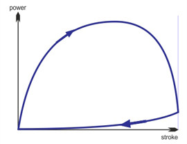
is a value of shock energy that is absorbed or transferred into a heat. The absorbed energy can be found based on different values of shock and recoil energies. The energetic capacity of hydraulic bumper is a function of lift, force and effectiveness. The value of damping in percentage is based on the ratio of real course of force diagram to the rectangle surface limited by values of final force and lift of bumper.
In an ideal case, the curve of bumping can be drawn in rectangle shape. Such course does not corresponds to practical conditions. The dumping d is a ratio of received work We to the performed work Wa. With the correct design of regulating mandrel, the effectiveness of hydraulic dumper is better than 90 %.
%
Better efficiency
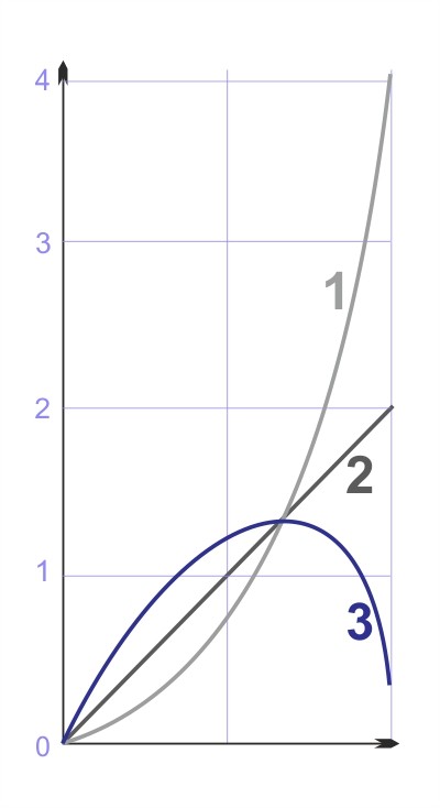
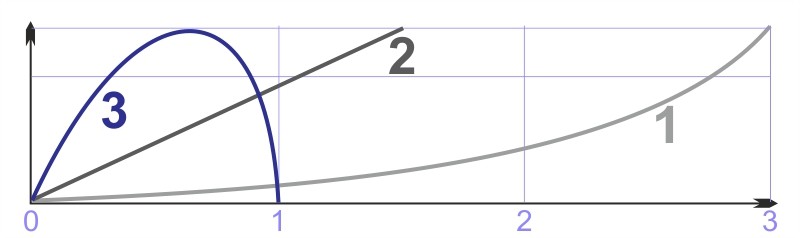
Hydraulic dumper compared with other damping systems
- rubber dumper
- spring dumper
- hydraulic bumpers
Constant lift
The final force in reverse ratio to the shock effect increases with the same lift.
Constant final force
The lift of damper shall be increased in reverse ratio to the effectiveness with the same final force.
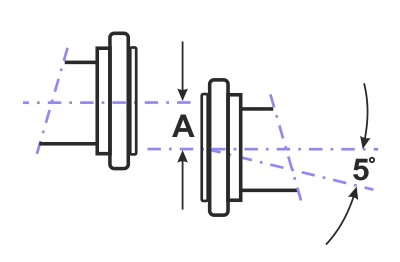
Maximum allowable slant shock
The hydraulic-gas bumper is designed for standard operational temperature from – 40 °C to +80 °C.
The short-term exceed of maximum operational temperature is possible for standard version of bumper. Provided the surrounding temperature in the area is still above 70 °C, we recommend the use of high-temperature sealing that enables the operation within the scope from + 80 to 120 °C.
If a large number of shock is made under such higher temperature, consult the supplier.